 On a global basis, it is estimated that 33 billion cubic meters of treated water is lost at an estimated cost of $15 billion (U.S.) per year. North America seems to be lagging behind in its awareness of this issue but is gradually catching up to the rest of the world. ?
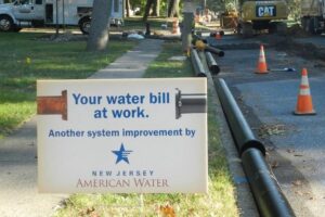
Water loss, also known as non-revenue water (NRW), is a significant problem worldwide in potable water distribution systems. System losses vary by utility; however, water losses ranging from 15 to 70 percent are common. The Ontario Sewer and Water Association stated that in Canada, up to 30 percent of treated water goes into the ground.
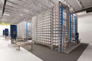
When a utility undertakes a major water loss project, multiple control zones with a single source of water (if possible) are required. These zones are referred to as District Metered Areas or DMAs. It is common for a mid- to large-sized utility to establish hundreds of DMAs. Assuming residential, commercial and industrial users are being metered, you now have measured flow into the DMA as well as flow to your users. There is a direct correlation to pressure and leakage; if you reduce pressure by 1 percent, you will reduce leakage by approximately 1.15 percent (subject to variation). The goal then is to develop multiple smaller DMAs within a utility and give clients just enough pressure to serve their needs while eliminating over pressures. It is common knowledge that a good pressure management approach is one of many solutions to reducing water loss, and it is typically the most economical approach with immediate results.
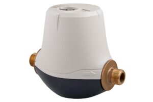
Each DMA requires a meter as well as a pilot-operated control valve. These valves are built to different standards worldwide and vary from manufacturer to manufacturer. Different quality materials may be used by different manufacturers. There are also many options that can be added to increase the life of these valves or to make maintenance easier. The American Water Works Association (AWWA) has a standard (Standard C530) for pilot-operated control valves that is highly recommended.
Here are some options when it comes to pilot-operated control valves for reducing pressure and leakage:
Standard Pressure Reducing Valve
A standard pressure reducing valve (PRV) is familiar to most users worldwide. For a utility that is undertaking pressure management and establishing DMAs, this is often an excellent selection. This valve has typically one pilot and one pressure setting. The pilot is manually set to the one pressure you desire downstream and that is the pressure you get. Downstream pressure setting is maintained as a constant regardless of varying upstream pressures or flow rates. This style of valve needs a differential pressure of 10 psi or 0.6 bar between the inlet and outlet of the valve to function effectively. To change pressure, the operator must adjust the valve manually by changing the pressure setting on the pilot. This style of valve works very well with medium to high system pressures. If available pressure differential drops below 10 psi (0.6 bar), pressure reducing valves cannot open fully, and as the available pressure drop is further reduced, flow approaches zero.
Low Pressure PRVs
If very low pressures are encountered during peak demand periods, standard PRVs cannot supply the required flow. If inlet pressures drop below 10 psi, the differential pressure across the valve is not enough to maintain the valve in the open position. The valve capacity is reduced and downstream customers may not have enough water. This issue can be overcome by using two pilots. The first pilot is a standard PRV pilot that is used to control or reduce pressure at non-peak usage periods. The second pilot is a modified altitude pilot that allows the main valve bonnet to vent to atmosphere at a predetermined low pressure (usually just below the downstream set-point). When the inlet pressure drops below the low pressure set-point, the main valve opens fully, minimizing pressure loss through the fully open valve at peak demand periods. The valve can open fully even with pressures as low as 2 psi (0.13 bar).
 A standard PRV typically has the pilot set for the lowest pressure required at peak demand to make sure that all users have enough pressure to satisfy their needs. Remember that the outlet pressure setting remains constant, regardless of variances in inlet pressure or flow rate. At non-peak usage periods (night), there is less demand on the system so pressure loss though the distribution and service mains is much less, resulting in higher downstream pressures especially in areas remote from the PRV. At non-peak times, the increased pressure has two negative outcomes:
1) Leakage rates increase.
2) Pipe bursts tend to correspond to higher pressure periods.
Those two outcomes can be overcome in part by using two standard PRV pilots on the main valve. One PRV pilot is set for the high demand pressure (day time) while the other pilot is set for low demand pressure (night time). A solenoid valve is supplied and a basic timing controller decides which of the two pilots is utilized based on the time. Depending on availability of power, a standard solenoid with a locally sourced timing device may be used or, alternately, if no power is available, a battery operated timer (submersible) combined with a latching solenoid valve using minimal power may be utilized. The above options can be very economical with excellent results. One consideration is the fire department minimum pressure requirements.
PRVs: Self Adjusting Based on Flow (Pressure/Flow Control)
Combination pressure/flow control valves can be a very interesting option. This type of valve senses flow through pressure differential across either a correctly sized orifice plate or a partially open gate valve downstream of the PRV. The standard PRV pilot has a large secondary diaphragm operator that adjusts the pilot set-point based on flow. The PRV pilot is set for minimum (night) pressure. The secondary operator then increases the set point as the flow increases. Minimum set point and pressure increase are determined to assure adequate pressure in all parts of the DMA at peak demand. Limitation of this style of valve is that it must be a single source to a DMA. Multiple valves feeding a DMA will not function correctly.
PRVs Incorporating Third Party Control: Time Switched or Flow Modulation
When utilizing this type of control, a standard PRV, complete with main valve and pilot, is utilized. A third party manufacturer of controllers and interface units will adapt its equipment to interface with the PRV manufacturer?s pilot. Typically, a Bias chamber will be mounted under the pilot or an actuation device will be mounted on top of the pilot depending on the controller manufacturer.
Flow modulation will react to flow variations in the system and adjust the pressure accordingly. If flow modulation is not required, then time-based control can be utilized with this equipment as an option. ?
PRVs Utilizing Motor-Driven Pilot Interfacing with SCADA
In this case, a sturdy slow speed 24 VDC (AC option available) motor operated device is fitted to the top of the pilot and attaches to the adjustment screw. This device requires less than 1 amp to operate and is controlled by a 4-20 mA signal from the water distribution SCADA system. The very low power requirement lends itself well to a solar powered self-contained station. Extended power failure would result in constant pressure at the last setting.
Pressure transmitters (upstream and downstream) can be used in conjunction with flow transmitters at the DMA so that real time data is available on SCADA. This information allows continuous adjustments of pressures based on flow demand.
PRV Pre-Packaged Systems
Utilities throughout the U.S. and Canada are utilizing pre-packaged systems on pressure reduction stations. These pre-packaged stations make sense for use in DMAs because they are built in a clean environment, pre-tested, quicker to install on-site and can be custom designed and often are more economical.
Brad Clarke is vice president of sales and marketing for Singer Valve Inc., a global designer and manufacturer of automatic control valves.?


Leave a Reply