

Check Out the Hydraulic Institute’s Data Tool for Pump Systems
By Isaac Holowell & Peter Gaydon
Engineering professionals often find themselves in need of comprehensive pump system information when performing work related to water and wastewater conveyance. The ability to quickly and easily access pump system details such as pumping descriptions, fluid property data, equations and calculators, that are arranged in a user-friendly tabulated way, can prove invaluable when analyzing and designing conveyance systems. One notable and free offering from the Hydraulic Institute (HI) that is sometimes overlooked by industry professionals is the HI Data Tool.
The HI is a non-profit organization dedicated to advancing the pump industry. For more than 100 years, HI has developed globally recognized pump standards and guidelines covering aspects of pump design, performance, installation, operation, maintenance and testing. Over the last 25 years, the offerings have been expanded to include pump and system training, certifications and tools for pump users and specifiers.
HI Data Tool
The HI Data Tool is a comprehensive technical resource for pump systems. It serves as an extensive guide for pump users, manufacturers, and engineers, offering resources for pumps and systems, calculators, and unit converters. The tool includes definitions, resources, references, fundamental knowledge about pumps and systems, interactive pump system demonstrators, fluid property data, fluid flow equations and user-friendly pump system calculators. It covers topics such as net positive suction head (NPSH), pump and system curves, frictional losses in piping systems, and more.
The HI Data Tool resembles a pump system engineering handbook, featuring a navigation bar that can be expanded to find specific topics of interest. However, it also includes features and benefits found on modern websites, such as tools to easily find words or topics using site search, a toggle function between U.S. and Metric units, interactive demonstrations, and time saving calculator tools. A useful resource within the HI Data Tool are the calculator tools. The Tools section includes unit conversions, a pipe friction loss calculator, tank volume calculators, atmospheric pressure calculators and line shaft bearing loss calculator.
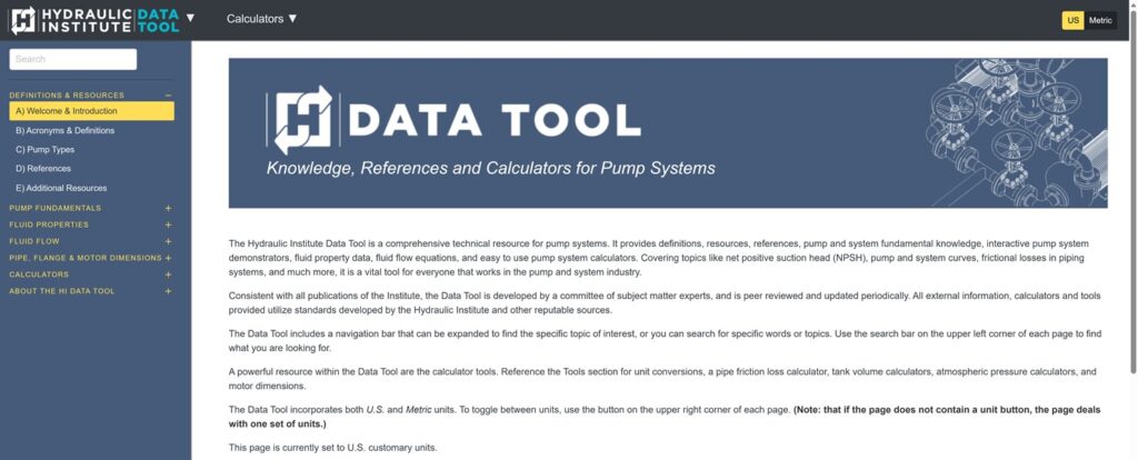
The tool leverages standards developed by HI and other reputable sources, and its data library is frequently updated with new information. Consistent with all HI publications, the HI Data Tool is developed by a committee of subject matter experts and is peer-reviewed. As such, the information presented can be deemed trustworthy since it has industry consensus. All external information, calculators, and tools provided adhere to standards developed by HI and other reputable sources.
HI Data Tool Development
In 2021, the HI created an initial release of a pump systems information data tool named the “HI Engineering Data Library.” The data library was modeled after the HI Pipe Friction Manual and the subsequent Engineering Data Book, which originally dated back to the 1940s, but a key objective at HI was to provide more modern resources in a format that served a new generation of engineers. A few years later in 2024, HI released a second version of the tool that was branded “HI Data Tool.” The new version restructured the navigation menu and added a preface section covering definitions, pump types, references and resources. HI also renamed the section headings and reorganized sub-sections.
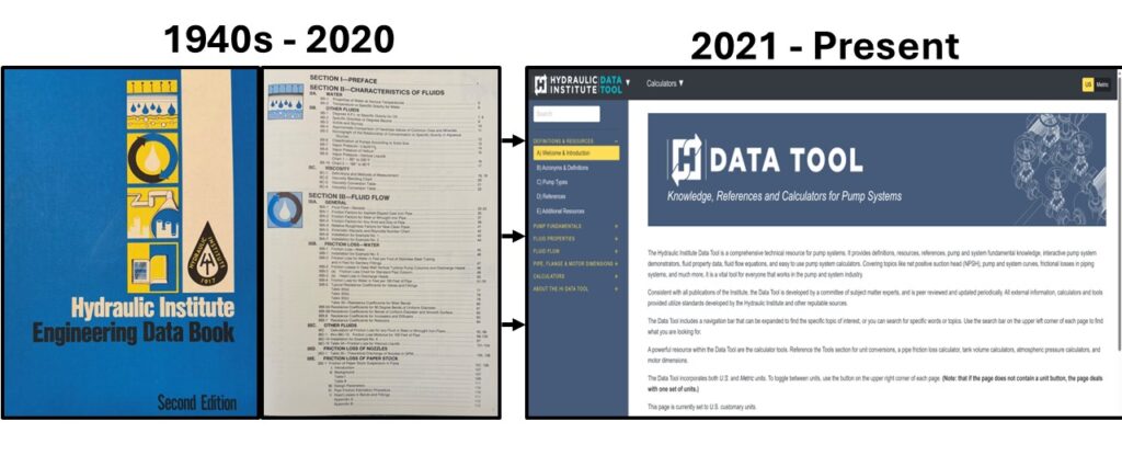
The HI Data Tool has tabs that provide collated information and resources on Pump Definitions and Resources; Pump Fundamentals; Fluid Properties; Fluid Flow; Pipe, Flange and Motor Dimensions; and Calculators. Additional details about the information included in the section tabs of the current version of the HI Data Tool are provided below.
Definitions and Resources
The Definitions and Resources section is new section revealed in the 2024 release of the HI Data Tool. This section provides a table of acronyms and definitions, pump type descriptions, references and additional resources, further explained as follows:
- Acronyms & Definitions for centrifugal, mixed flow, axial flow, rotary and reciprocating pumps, and pump system terms that are used within the HI Data Tool are included. The industry source is provided for the definition, and a link is provided to the HI Data Tool section where the term is used or discussed.
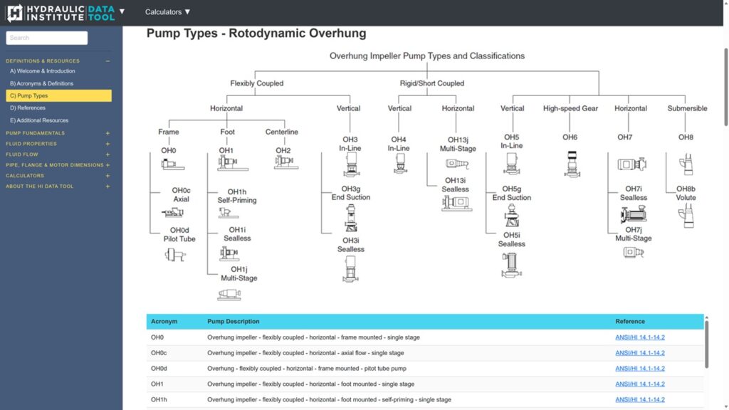
Pump Types are standardized with descriptions and acronyms, along with the related industry standard. An index for multiple pump types, including details and schematics, is provided.
- Rotodynamic pumps include centrifugal, mixed and axial flow pumps. Positive displacement pumps are divided into reciprocating types, which use pistons, plungers and diaphragms, and rotary types that use screws, gears, lobes, vanes or other meshing components.
- References and Additional Resources are aggregated, which provides peer-reviewed standards, guidelines, guidebooks and technical papers published by HI and other American National Standards Institute (ANSI) accredited standards developers. The additional resources provide content that is mostly free that users can reference for additional learning, such as pump frequency asked questions and technical blogs.
An example from the Pump Types section showing overhung pump types, with descriptions and associated reference standards is shown below.
Pump Fundamentals
The updated version of the Pump Fundamentals section was updated to include interactive educational demonstrators, equation formatting, figures, and a new section on submergence. The Pump Fundamentals section covers:
- The System Curves section which includes pressure and head relationship, static head, frictional head loss, and methods to determine the system curve.
- The Pump Curves sectiondemonstrates how pump curves are drawn and related, as well as affinity rules, information on series and parallel pump curves, and considerations for operating regions.
- The Combined Pump & System Curves section covers the interaction of the pump and system curve, the operating point and methods to change the operating point.
- The Pump Principles sectioncovers specific speed, generally attainable efficiency, impeller types, NPSH, suction specific speed, and cavitation.
- The Submergence section is new and highlights the importance of minimum submergence to limit free surface vortices and provides information on industry standards.
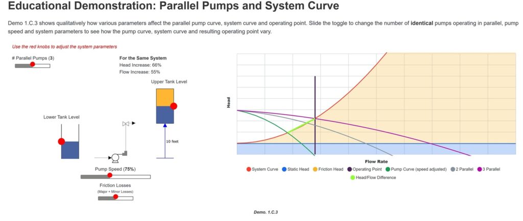
Shown below is an example from the Interactive Parallel Pump and System Curve Demonstrator that illustrates how system curves change with varying levels, pressure and frictional losses, and how the pump curve and operating point varies with additional pumps operating at varying pump speeds.
Fluid Properties
The Fluid Properties section was also updated to have better table navigation so that users can more easily navigate the tables to find the properties they are looking for. The Fluid Properties section covers:
- Water section covers properties at various temperatures, saturation properties, and other critical information in interactive tables and graphs.
- Solids and Slurries section covers methods to calculate the effect of slurry concentration on specific gravity, hardness values of ores and minerals, and slurry classification.
- Viscosity section provides definitions, equations, methods to measure, conversions, and information on Newtonian and non-Newtonian liquids.
- Other Fluids section covers degrees A.P.I and specific gravity of oil along with property data for other commonly pumped liquids.
Fluid Flow
In the updated version of the Fluid Flow section, content was rearranged in the pipe frictional losses and losses in valves, fittings, and bend subsections. The Fluid Flow section covers:
- The Pipe Frictional Losses section provides methods to calculate frictional head loss based on the Darcy-Weisbach friction factor, and the methods outlined are used in a calculator for Frictional Losses in Pipes.
- The Losses in Valves, Fittings, and Bends section provides typical resistance coefficients and details how to calculate frictional head loss through the fittings.
- The Losses with Other Fluids section refers users to the calculator for Frictional Losses in Pipes, which allows the user to change the viscosity and specific gravity of the fluid to see the effect on frictional head loss.
- The Losses in Nozzles section provides a formula to calculate nozzle flow and a table of theoretical discharge flow based on pressure head and nozzle size.
- The Losses with Paper Stock section details a collection of information from the Technical Association of Pulp and Paper Industry (TAPPI), and other reputable resources in the chemical and mechanical pulp industry, on how to determine frictional head loss based on the pulp type and velocity.
Pipe, Flange & Motor Dimensions
The Pipe, Flange & Motor Dimensions section is also a new addition in the Second version of the HI Data Tool. The section includes characteristics of various pipe materials, flange dimensions for various American Society of Mechanical Engineers (ASME), American Society for Testing and Materials (ASTM) and American Water Works Association (AWWA) standards, and National Electrical Manufacturers Association (NEMA) horizontal, vertical, and JM- and JP-type face mounted close-coupled motors.
The Pipe, Flange and Motor Dimensions section covers: Steel Pipe, Stainless Steel Pipe, Ductile Iron Pipe, Non-Ferrous Pipe and Tube, Plastic PVC Pipe, Flange Dimensions, and Motor Dimensions.
Calculators
This Calculators section is designed to help the user work more efficiently, and the updated version includes additional unit conversions, updated epsilon values for nonferrous materials in the friction loss calculator, added PVC pipe to the friction loss calculator, and added subsections covering line shaft bearing losses, tank volume calculators, and the elevation effect on atmospheric pressure.
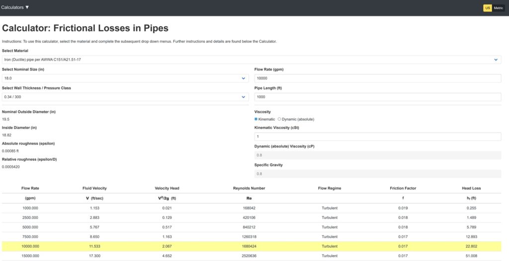
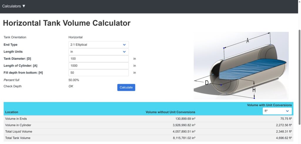
The Calculator section includes Unit Conversions, Kinematic & Dynamic Viscosity Conversions, a Pipe Friction Loss Calculator, a Line Shaft Bearing Loss Calculator, a Volume Calculator for Horizontal, Vertical and Spherical Tanks, and an Effect of Elevation on Atmospheric Pressure Calculator. Images from the Pipe Frictional Head Loss Calculator and Volume Calculators for Horizontal, Vertical and Spherical Tanks are shown below. The Pipe Frictional Head Loss Calculator is based on standard pipe dimensions utilizing the Darcy-Weisbach friction factor calculated from the Colebrook-White equation.
Summary
To meet the needs of industry professionals who seek easy access to a wide range of pumping resources, HI developed the HI Data Tool as a platform for the exchange of consensus peer-reviewed industry information among pump manufacturers, end users, and engineers. Access to the tool can be found at datatool.pumps.org.
As many in the industry have come to realize, the HI Data Tool can serve as a vital implement for everyone that works in the conveyance system industry. HI’s goal is to help raise awareness of this free tool to help conveyance professionals efficiently and comprehensively deliver water and wastewater pumping work products.

Isaac Holowell, P.E., is an environmental engineer at CDM Smith in Fort Meyers, Florida. He has more than 12 years of experience in hydraulics engineering, hydraulic profile modeling of water/wastewater facilities, pumping systems, pump station design, transient analyses and construction. He is an active member of the Hydraulic Institute Waterhammer Committee and Engineering Data Tool Committee.

Peter Gaydon is the deputy executive director at the Hydraulic Institute (HI) in Parsippany, N.J. Gaydon oversees standards, technical resources, training and certification programs at the Hydraulic Institute. He serves as a member on several pump related standards committees associated with AWWA, CSA and ASME. He serves as the Chair for the AWWA E103 Vertical and Horizontal Line-Shaft Pumps committee.











Leave a Reply